 True Balancing is an active balancing technology. which means it moves energy from cell to cell. Moving energy from cells at high state of charge (SOC) to cells at low SOC balances the battery.
Voltage sensors are connected to each cell. Cell voltages indicate the relative SOC of each cell. This lets True Balancing know which cells need more energy to keep them in balance with the rest of the battery.
True Balancing uses a technology called switch mode voltage dividers (SMDs) to move energy from cell to cell. SMDs are common, simple, low-cost, highly efficient circuits. Switch mode technology is at the heart of almost every consumer-grade power supply made today.
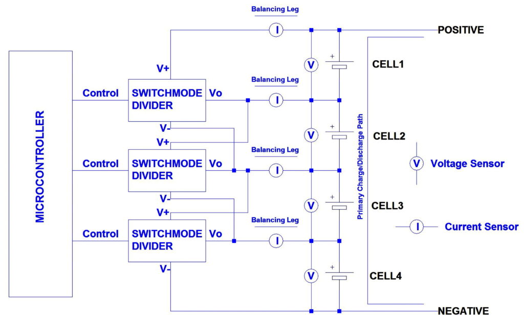
When True Balancing is balancing the battery, it moves electrical energy on paths called “balancing legs”. Each balancing leg has a current sensor. The current sensors have two functions.
First: We monitor the current that is flowing on each balancing leg to make sure it doesn’t get too high. This allows safe, reliable operation of True Balancing.
Second: With measurements of voltage and current at each cell, we can calculate the impedance of each cell. This is the feature that really unlocks the power of True Balancing.
If you know voltage, current and impedance on a cell by cell basis, and if you can selectively move energy to or from any cell in the battery, you have a level of control that is unprecedented in cell balancing. This enables the unique benefits of True Balancing.
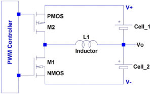
A switch mode divider (SMD) is a switch mode regulator that is configured as a voltage divider. Switch mode regulators are well known, widely used, low cost and highly efficient. Virtually every power supply for charging cell phones, tablets, laptops, etc. uses switch mode technology.
In True Balancing, the SMD divides the voltage of two cells connected in series. A PWM signal is applied to the FETs. The duty cycle of the PWM signal determines the output voltage of the SMD (Vo). Vo can be any voltage between V+(positive terminal of the upper cell) and V- (negative terminal of the lower cell). Adjusting the duty cycle to above or below 50% allows energy to be moved from cell 1 to cell 2 or vice versa.
Switch mode regulators are extremely efficient (i.e. very low impedance). The high efficiency, low impedance characteristics of the SMD enable high balancing currents.
Energy is always moved from higher SOC cells to lower SOC cells, so the regulator always operates in buck mode, further increasing efficiency.
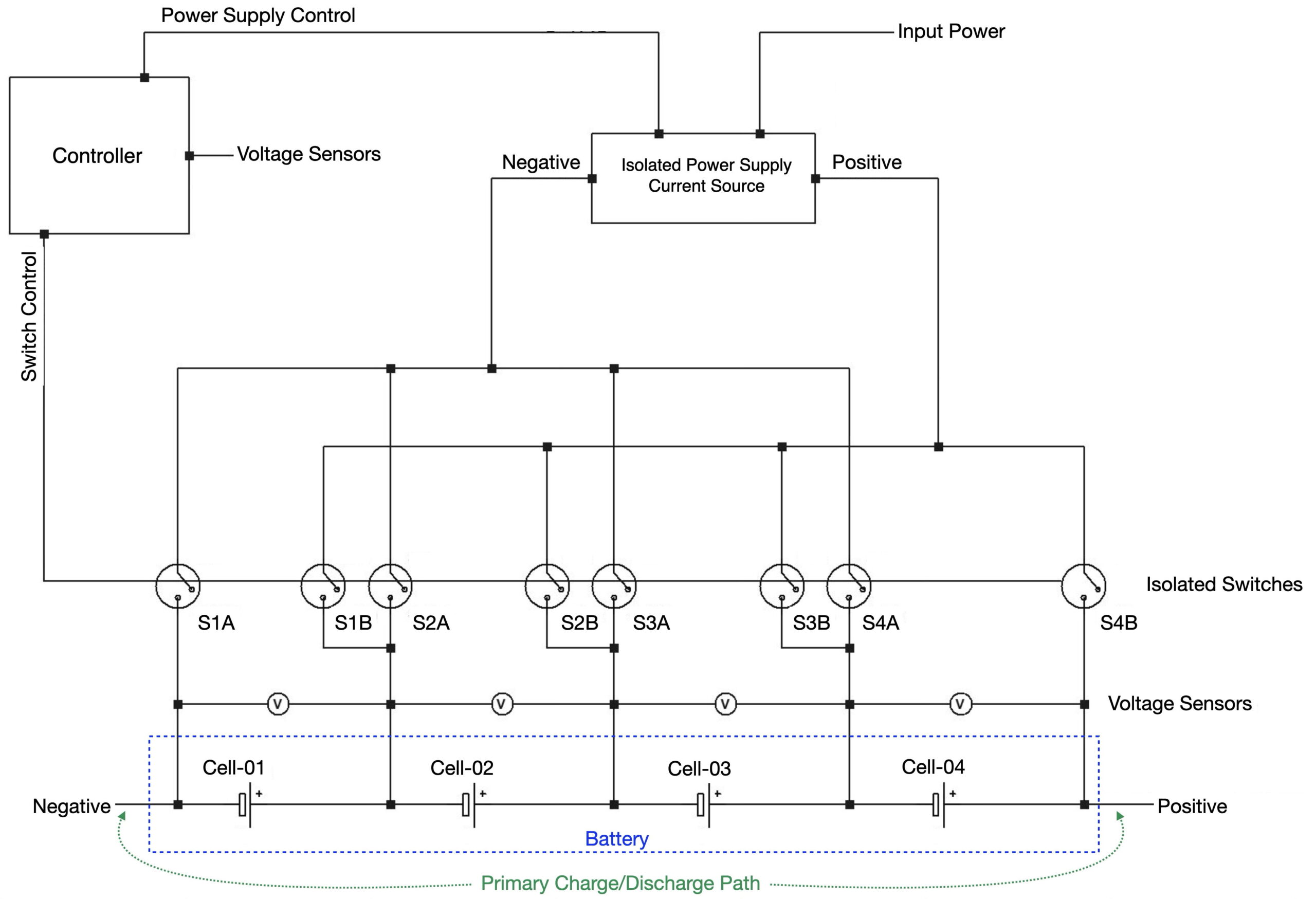
As shown in the circuit diagram above (and below), a complete True Balancing system consists of a series of interleaved SMDs, which allows energy to be transferred from any cell in the series stack to any other cell in the series stack.
True Balancing uses SMDs to move energy from the primary charge path to any cell in the stack (when balancing during charge) or to move energy from cell to cell (when balancing during discharge or while the battery is idle). This is an extremely efficient means of moving energy.
The output voltage (Vo) of each SMD is connected to a node between two adjacent cells. The high rail of each SMD (V+) is connected to the positive terminal of the cell on the high
side of the node. The low rail of each SMD (V-) is connected to the negative terminal of the cell on the low side of the node.
Modulating the PWM control signal to the SMD allows the value of Vo to be set to any voltage between V+ and V-. This allows energy to be diverted off of the primary charge path and moved to any cell in the stack. Energy can be moved in either direction – up or down the stack.
Voltage sensors are connected in parallel to each cell in the stack. The microcontroller (μC) samples data from the voltage sensors to determine the relative SOCs of the cells. This identifies cells at lower SOC that need more energy to bring them into balance with higher SOC cells.
Lithium-ion cells are very low impedance, as are SMDs. So this circuit architecture consists of a series of interleaved low-impedance, high-gain control loops. This is an unstable architecture with risk of runaway current conditions.
To eliminate this risk, current sensors are placed on each balancing leg. The μC monitors the current sensors whenever True Balancing is active. If current on any balancing leg approaches a threshold level, the PWM signal to the associated SMD is adjusted to prevent the balancing current from exceeding the threshold. The threshold can be set with any desired safety margin, thereby creating a safe, stable and effective system.
The current sensors on the balancing legs yield an additional advantage. Data from the voltage and current sensors allows us to calculate impedance on a cell-by-cell. Sampling the sensors at a regular frequency allows us to calculate dynamic impedance (dV/dI). Having values of dynamic impedance in real-time on a cell-by-cell basis provides critical information that allows unprecedented and very fine control over the state of the entire pack.
True Balancing can measure cell impedance at controlled currents (both charge and discharge). This allows accurate characterization of individual cell impedances (both resistance and reactance). The ability to measure cell impedance provides unprecedented insight into the conditions of individual cells.
Click on the “Next” button to start a set-by-step walkthrough of the logic.
The voltage sensors across each cell are sampled regularly to see if any cell has reached full charge voltage.
If all cells are below full charge voltage, charge current continues to flow down the primary charge path.
The control signals to the switch mode dividers are modulated to divert energy off of the primary charge path and bring energy to cells that are still below FCV.
Charging (or balancing) current bypasses any cells that are at FCV.
If current on any balancing leg reaches the threshold, the control signals to the relevant SMDs are adjusted to bring balancing current back below the threshold.
At this point the charge cycle enters constant voltage (CV) phase.
During the CV phase of charging, current sensors on the balancing legs are monitored regularly. When current to any cell drops below a threshold (the cut-off current, or COC), that indicates that the cell is fully charged.
Each cell will reach full charge at a different time. When a cell reaches full charge, True Balancing diverts energy around that cell and continues charging cells that have not yet reached full charge. True Balancing continues to operate this way until every cell in the pack has reached true full charge.
Every cell in the battery, and thus the entire battery, is brought up to true full charge at the end of every charging cycle, regardless of cell chemistry and regardless of the conditions of the individual cells in the battery.